
Getting the Kaiser running (Part II)
Wiring the car was next on my list, the engine is complete with no wiring harness to connect to the computer and I made the decision to use the harness from the 302 that was in the 51 - 4 door rather than buy an aftermarket wiring systems for $550.00.

The EFI that was in the 51 is out of a 91 Ford Crown Victoria where the air intake and throttle body are on the driver side, the 302 HO engine and EFI are out of a 91 Mustang where the air intake and throttle body are on the passenger side. So the harness was taken apart by removing the tape, tie wraps, and some of the heat shrink, then laid out on the Kaiser engine with the connectors plugged into the sensors, where some were on left side of the manifold and now on the right, and to make sure the exhaust oxygen and transmissions speed sensor connectors would reach. All the wires were long enough except the mass air flow sensor that had to be lengthened then the harness was re taped with heat shrink put back where it could fit.


A hole was cut in the fire wall large enough for the 20 pin connector and relays to fit through with the EFI computer mounted on the back of the fuse panel plate (between the fire wall and mounting plate) and the fuse panel, relays 12V to 6V power unit and starter relay on the front.

A complete wiring systems was purchased from Ron Francis, that included the head light switch, dimmer switch, 12V to 6V unit, pre-wired fuse panel with all necessary relays and flasher. The wiring inside the car was run and connected while any wires that had to be pulled back inside when the body is removed for paint were coiled up and tagged. The Air Ride system and battery were installed in the trunk with the positive cable, air ride harness, rear light, audio and other wire running along and through he drive line tunnel (the wire way was shown in the last posting).


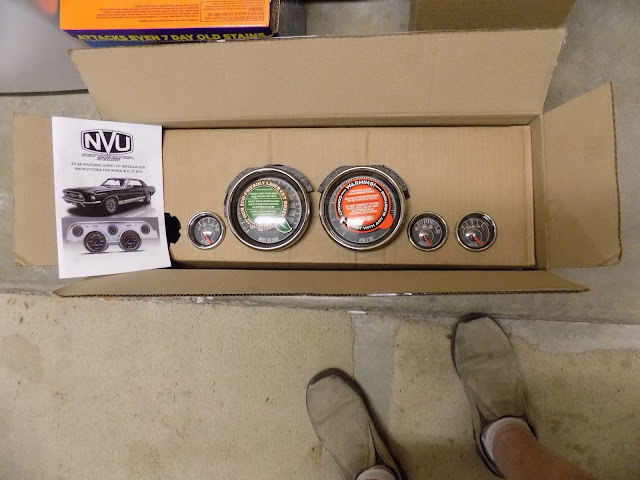
The instrument cluster/speedometer has been sent to the Red Line Gauge for rebuilding and to convert the amp meter to a volt meter

so the wires are pulled out at the cluster location. All other switches are installed with the original wiper switch and motor connected to the 12V to 6V unit. The Air Ride controller opening was cut in the center console then the console was reassembled and installed along with the Vintage Air A/C unit, controls and air duct hoses then wired using plug in connectors (where necessary) to allow the center console removal later.

I added terminal strips, one in the trunk and 3 under the dash for the multiple wire connections necessary for interior lights, door switches, ground connections, radiator fan power and controls.

I disconnected the starter cable, taped off all unconnected power and ignition wires then connected the battery and tested the wiring including firing up the Air Ride System and programming its computer for the ride height (3) settings.
The only major problem that occurred is an air leak that I couldn't find and had to have my wife come out and listen (she has very good hearing) for the leak. Turned out to be in the air compression where an O ring was not installed properly by the manufacturer.

The EFI that was in the 51 is out of a 91 Ford Crown Victoria where the air intake and throttle body are on the driver side, the 302 HO engine and EFI are out of a 91 Mustang where the air intake and throttle body are on the passenger side. So the harness was taken apart by removing the tape, tie wraps, and some of the heat shrink, then laid out on the Kaiser engine with the connectors plugged into the sensors, where some were on left side of the manifold and now on the right, and to make sure the exhaust oxygen and transmissions speed sensor connectors would reach. All the wires were long enough except the mass air flow sensor that had to be lengthened then the harness was re taped with heat shrink put back where it could fit.


A hole was cut in the fire wall large enough for the 20 pin connector and relays to fit through with the EFI computer mounted on the back of the fuse panel plate (between the fire wall and mounting plate) and the fuse panel, relays 12V to 6V power unit and starter relay on the front.

A complete wiring systems was purchased from Ron Francis, that included the head light switch, dimmer switch, 12V to 6V unit, pre-wired fuse panel with all necessary relays and flasher. The wiring inside the car was run and connected while any wires that had to be pulled back inside when the body is removed for paint were coiled up and tagged. The Air Ride system and battery were installed in the trunk with the positive cable, air ride harness, rear light, audio and other wire running along and through he drive line tunnel (the wire way was shown in the last posting).


The instrument cluster/speedometer has been sent to the Red Line Gauge for rebuilding and to convert the amp meter to a volt meter

so the wires are pulled out at the cluster location. All other switches are installed with the original wiper switch and motor connected to the 12V to 6V unit. The Air Ride controller opening was cut in the center console then the console was reassembled and installed along with the Vintage Air A/C unit, controls and air duct hoses then wired using plug in connectors (where necessary) to allow the center console removal later.

I added terminal strips, one in the trunk and 3 under the dash for the multiple wire connections necessary for interior lights, door switches, ground connections, radiator fan power and controls.

I disconnected the starter cable, taped off all unconnected power and ignition wires then connected the battery and tested the wiring including firing up the Air Ride System and programming its computer for the ride height (3) settings.
The only major problem that occurred is an air leak that I couldn't find and had to have my wife come out and listen (she has very good hearing) for the leak. Turned out to be in the air compression where an O ring was not installed properly by the manufacturer.


Comments